Circuit Diagram Of Boost Converter
Boost converter circuit schematic kickback inductive charging simple gif prototype electric self car understanding viewed kb times Boost converter circuit 555 Circuit diagram of boost converter
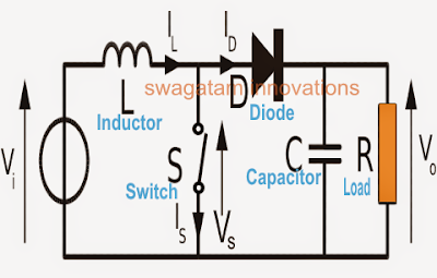
What is Boost Converter? Operating Principle and Waveform
Boost converter dc arduino circuit lm2577 feedback schematic diagram potentiometer electronoobs code Dc boost converter circuit 3.3-5v to 12v-13.8v Circuit boost 5v diagram 8v eleccircuit 7v output 3v 6v circuits input convert charger amplifier diagrama wiring r53 datasheet schematics
Boost converter circuit 555
Boost converter circuit 5v using diagramPower supply Circuit diagram of the boost converter.Dc to dc boost converter circuit (part 5/9).
Boost converter circuit using 555 timer icVariable output voltage dc to dc boost converter circuit diagram using Circuit diagram of boost converterDc to dc boost converter circuit (part 5/9).

5v boost converter
Converter circuit unidirectionalBoost converter circuit 5v converter boost diagram circuit 2a icBoost converter.
Diode capacitor schottky resistor inductorDc to dc boost converter circuit homemade High power boost converter circuit diagramHow to make a boost converter circuit.

Boost converter basic circuit electronics converters
5v boost converter1 circuit diagram of boost converter. 5v boost converterIdeal unidirectional dc-dc boost converter circuit.
How to build a dc-to-dc boost converter circuitCircuit converter boost dc diagram part Boost eleccircuit 5vBoost converters.

What is boost converter? operating principle and waveform
Converter boost diagram circuit10+ boost converter circuit diagram Converter boost circuitProteus boost circuit converter diagram software.
Boost converter circuit diagram with explanationI like free ware files: boost converter schematic Converter boost power circuit high diagram gadgetronicx step circuits voltage diyBoost converter circuit using mc34063 ic.

Converter boost circuit diagram loading dc
Get torrents from my blog: buck boost converter circuitBuck converter circuit boost voltage circuits power dc ac diagram supply gr next torrents battery Schematic diagram of the boost converter circuitBoost converter converters work circuit homemade capacitor relay voltage.
Boost converter diagram dc simple circuit topology conduction converters voltage mode output discontinuous analysis schematic engineering equilibrium low four current555 boost converter circuit ic components timer using transistor capacitor bc547 npn required diode How boost converters workWhat is boost converter? circuit diagram and working.

Boost converter circuit schematic make electrical layout circuitlab created using stack
Simple boost converter circuitBoost converter circuit diagram in proteus software Circuit dc converter boost build inductor shown below breadboard above pdfBoost converter using ir2110 and pic microcontroller.
Boost converter circuit diagramConverter boost circuit load work power granted connections taken draw note something did please its .


