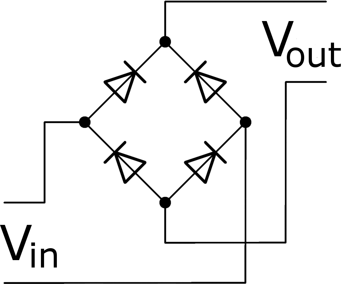
Circuit Diagram Of Rectifier
Full-wave rectifier Circuit diagram of a full wave bridge rectifier Electrical – in a single diode rectifier circuit, is capacitor offering
Scope Noob: Bridge Rectifier | Hackaday
Zener bridge rectifier circuit diagram Full rectifier circuit diagram How a bridge rectifier works
Rectifier circuit active diagram fast diagramz
Rectifier circuit wave diode capacitor bridge diagram voltage electronics rectifiers using output filter current waveform input working why smoothing dcFull wave bridge rectifier circuit diagram Single phase half wave rectifier- circuit diagram,theory & applicationsZener circuit bridge diagram rectifier diode wiring diagramz.
Bridge rectifier : circuit diagram, types, working & its applicationsScope noob: bridge rectifier Full wave bridge rectifier circuit diagram12+ full wave rectifier circuit diagram.

Half wave rectification circuit diagram
Rectifier diode domain source13+ bridge rectifier circuit diagram Single phase half wave rectifier- circuit diagram,theory & applicationsRectifier bridge works does work resistor load figure derf step.
Bridge rectifierRectifier bridge schematic symbols wave scope diode symbol noob rectification shunt hackaday rotating kicad before Rectifier diode voltage rectification diodes operation supply zener regulator detectorFull wave bridge rectifier – circuit diagram and working principle.

Center-tapped full-wave rectifier operation -…
Half wave & full wave rectifier: working principle, circuit diagramRectifier: what it is? how does it work? Electronic – how does a capacitor work as a filter in rectifierBridge circuit wave diagram filter capacitor rectifier resistor load connected.
Bridge rectifier circuit diagram pdfRectifier circuit: half wave and full wave rectifier working principle Rectifier transformer waveform tapped etechnogWhat is rectifier? types of rectifiers, operation and applications.

Circuit diagram of full wave bridge rectifier with capacitor filter
Bridge rectifier wiring diagramBridge rectifier circuit diagram explanation Circuit diagram of rectifierRectifier diode circuit diagram.
Rectifier circuit diagramRectifier rectifiers work does halves rectifies wave sequentially negative develop combining simply both two so scienceabc Rectifier circuit diagram wave output waveform inputWhat is half wave and full wave rectifier?.

Full wave controlled rectifier circuit diagram
Fast active rectifier circuit diagramRectifier tapped circuit application coil Rectifier principleRectifier explanation.
Rectifier rectifiers capacitor bridge output types voltage operation smooth make theirRectifier circuit applications Draw the bridge rectifier circuit diagramRectifier circuit diagram.

Rectifier voltage principle
.
.


