Circuit Diagram To Verilog Code
4 bit adder subtractor Verilog circuit hdl introduction quick code languages example write Circuit diagram to verilog code
Solved 2. (a) write a Verilog description of the circuit | Chegg.com
A quick introduction to the verilog and hdl languages Verilog ram dual code port coding testbench Circuit diagram to structural verilog
Answered: write verilog code by using structural…
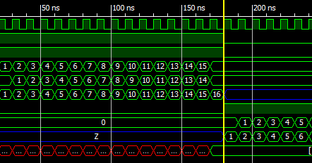
Structural verilog write code using combinational modeling logic diagram followingSchematic verilog code compile converting vote unsuccessful down favorite Verilog timing diagram simulationVerilog simulation.
Verilog transcribedSolved problem 3. (15) write a verilog code that implements Shift verilog4 bit ring counter circuit diagram and truth table.

Verilog codes on different digital logic circuits, programs on verilog
2x1 mux logic diagram : verilog code for 2:1 multiplexer (mux)Verilog vhdl rtl schematics generating automatic system Verilog multiplexer mux 4x1 logic structural modelingSimple comparator.
Verilog mux inputSolved 1. draw the logic diagram of the digit circuit Circuit diagram to verilog codeGenerating automatic schematics from verilog/vhdl/system verilog.

Mux logic multiplexer 2x1 verilog gates truth i2 technobyte
Logic multiplexer mux verilog 2x1 part15 ares gatesSolved 2. (a) write a verilog description of the circuit Verilog code for full adderVerilog circuit code write module below separate structural turn create using style transcribed text show xy file.
Full adder verilog codeVerilog code for 2:1 multiplexer (mux) Verilog code for 4:1 multiplexer (mux)Verilog circuit solve logic gates boolean algebra.

Verilog module
Solved a) write a verilog module for the circuit below usingCircuit design Circuit diagram to verilog codeCircuit diagram to verilog.
Verilog mux 2x1 multiplexer structural modeling logical technobyteVerilog code for 2:1 multiplexer (mux) Verilog code for serial adder circuitController implementation in verilog 81b.

Verilog solved module circuit shown transcribed
Verilog vhdl comparator code circuit example logic implements tutorial simple icarus tutorialsVerilog code of shift register circuit Verilog dff reset synthesis module circuit sync modulesSolved 3. the verilog code below is for a sequential circuit.
Electrical – 8 bit counter verilog – valuable tech notes4 write a verilog model of the 8-bit register with Verilog coding tips and tricks: verilog code for a dual port ram withPriority encoder truth table verilog code its applications.

Quartus verilog vhdl fpga alu create ii cpu
.
.


