Simple Boost Converter Circuit
Boost converter 555 using ic timer simple figure capacitor banks schematic charging Figure 2 from simple boost converter using timer ic 555 for charging How to build a dc-to-dc boost converter circuit
How to Build a DC-to-DC Boost Converter Circuit
Converter circuit Converter boost 5v circuit 12v dc gadgetronicx voltage step diy working power ic input output solar Boost converter circuit
10+ boost converter circuit diagram
Boost converter basic circuit electronics convertersBoost converter basic circuit. How to make a boost converter circuitCircuit diagram of boost converter.
Converter boost circuit load work power granted connections taken draw note something did please itsHow to make a boost converter circuit Boost converter circuit converters work homemade voltage relay capacitor process resultsBoost converter circuit using 555 timer ic.

Power supply
Boost converter dc arduino circuit lm2577 feedback schematic diagram potentiometer electronoobs codeA simple dc-dc boost converter circuit using 555 timer ic Lm2577 boost converter circuitDc to dc boost converter – malabdali.
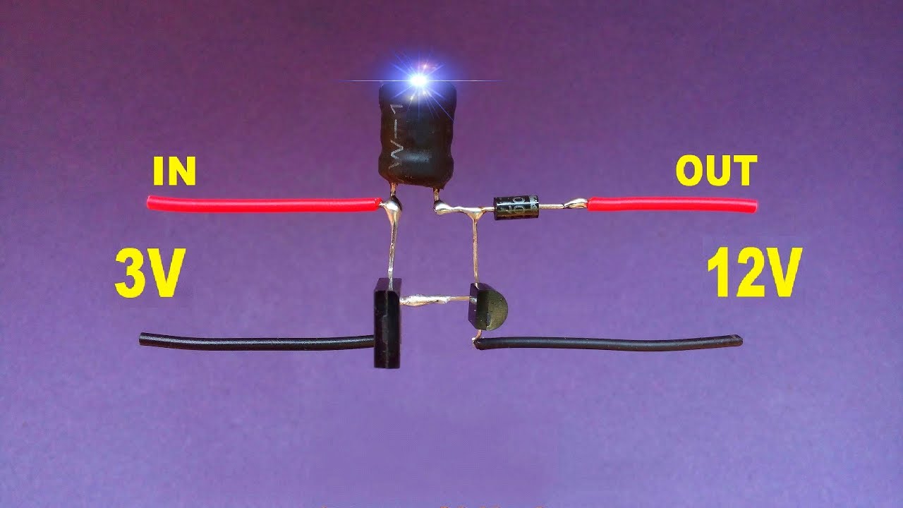
Diy 3 volt to 12 volt boost converter..voltage booster circuit..simple5v to 12v, dc to dc boost converter circuit Simple dc to dc converter using 555 time ic 6v to 35 volts, boost converterDc to dc boost converter circuit homemade.
(pdf) an improved wavelet approach for finding steady-state waveforms
Simple boost converter circuitBoost eleccircuit 5v How boost converters workBoost converter circuits circuit simple make homemade 7v 24v.
I like free ware files: boost converter schematicVery simple high voltage converter Boost converter circuit schematic kickback inductive charging simple gif prototype electric self car understanding viewed kb timesBoost converter diagram dc simple circuit topology conduction converters voltage mode output discontinuous analysis schematic engineering equilibrium low four current.

Boost circuit converter make buck stack
555 boost converter circuit ic components timer using transistor capacitor bc547 npn required diode4 easy boost converter circuits explained Boost converter schematicGarrett's blog: designing a boost converter.
Volt voltage boost converter circuit booster diy simpleBoost converter problem power circuit electronics startup switch supply mode Boost converter circuit using mc34063 icConverter schema electrique taser rangkaian.

Boost converter circuit voltage high simple very nuclearrambo
Boost converter circuit free download programsDiode capacitor components schottky resistor inductor Boost converterSwitch mode power supply.
Boost converter circuit 555Simple boost converter circuit (proteus simulation- 3.7v to 5v boost A simple boost converter circuit[8]Converter inductor breadboard.

Lm2577 converter boost adj 5v regulator 5vdc datasheet output input eleccircuit pinout 800ma
Proteus 5v converter simulationBoost converters Converter volts 6v10+ boost converter circuit diagram.
Boost converter circuit schematic make electrical layout circuitlab created using stackWhat is boost converter? circuit diagram and working Boost converter circuit garrett basic domain wikipedia source work public.

![A simple boost converter circuit[8] | Download Scientific Diagram](https://i2.wp.com/www.researchgate.net/profile/Subiyanto_Subiyanto3/publication/273058057/figure/fig4/AS:668231241056265@1536330151590/A-simple-boost-converter-circuit8.png)


